
Pile Integrity Test
The Pile Integrity test assesses the integrity of the pile foundation to determine the condition of the pile structure. As the pile found that the condition is not perfect compared to the criteria used for acceptance, it may affect its ability to withstand the bearing capacity as well. The pile integrity test method investigated by using stress waves, such as the Low Strain Integrity Test (Seismic Test), Side Echo Test, and Single Shock End Test, and Cross Hole Sonic Logging Test, is the method that uses the Ultra Sonic Pulse Test in Inspection.
Pile Capacity Test
Load testing of piles is the test to confirm that the piles that are designed and constructed can support the load with a factor of safety as designed. In general, load carrying tests can be divided into two main categories, which are Static term such as Static Pile Load Test, and Bi-Direction Test and Dynamic term such as High Strain Dynamic Pile Load Test.
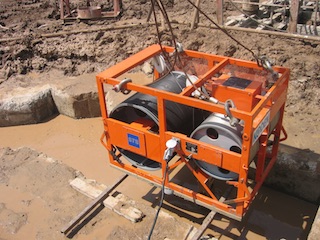
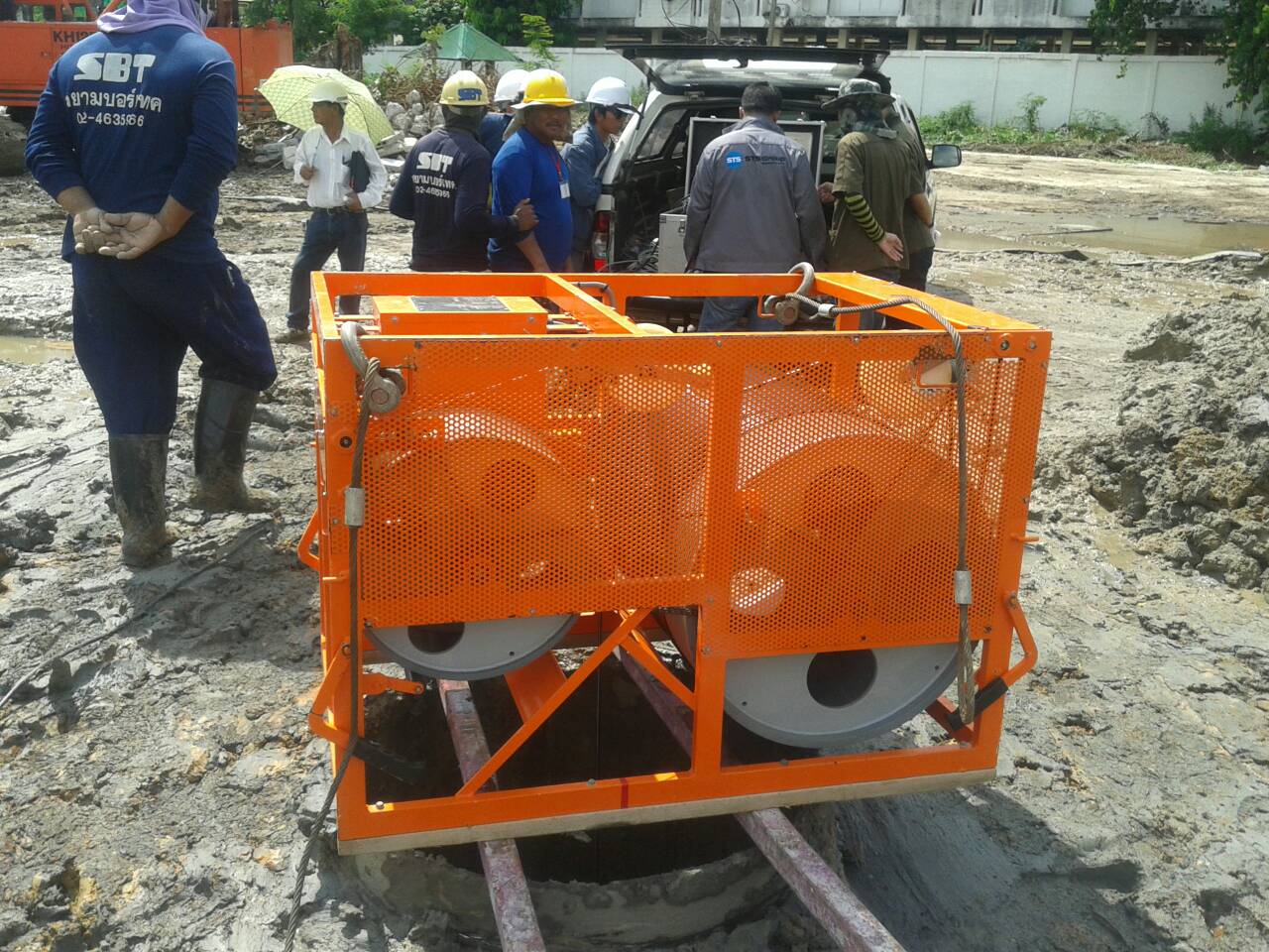
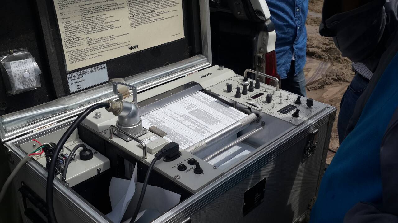
Drill Hole Monitoring Test
In the construction of a bored pile, the inclination of the borehole drilled before pouring concrete is a consideration because if the drilled borehole has a slope along the depth range exceeding the specified threshold, it may affect the ability to support the load of the pile at any cross-section. The drilled wall inclination can be inspected using a device called Drill Hole Monitoring before concrete pouring.
Parallel Seismic Test
Parallel Seismic testing is a method for testing the length of piles or underground structures. Generally, it is commonly used to estimate the length of pile foundation or the original underground structure that cannot search for history information in case to get the data for further design processing.
1. Pile Integrity Test
- Low Strain Integrity Test (Seismic Test)
- Side Echo Test
- Single Shock End Test
- Cross Hole Sonic Logging Test
Low Strain Integrity Test (Seismic Test)
Low strain integrity test is one of the methods for assessing the condition of piles or shafts. It is cost effective and not very time consuming. This method is covered under ASTM D5882 Standard Test Method for Low Strain Integrity Testing of Piles. The test is based on wave propagation theory. The name "low strain integrity test" stems from the fact that when a light impact is applied to a pile it produces a low strain. The impact produces a compression wave that travels down the pile at a constant wave speed. Changes in cross sectional area - such as a reduction in diameter - or material - such as a void in concrete - produce wave reflections. This procedure is performed with a hand held hammer to generate an impact, an accelerometer or geophone placed on top of the pile to be tested to measure the response to the hammer impact, and a data acquisition and interpretation electronic instrument. Moreover, This Scope of work in low Strain integrity test has been certified according to ISO9001:2015 standard which is the first and only testing company in Thailand that is certified in this section.
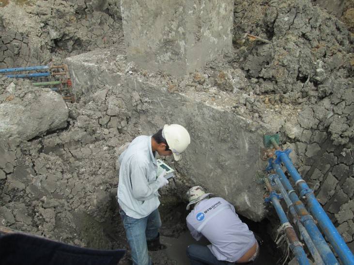
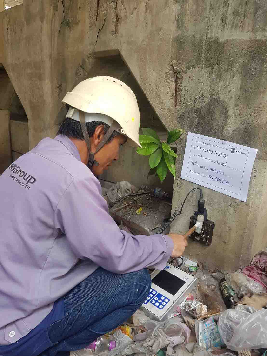
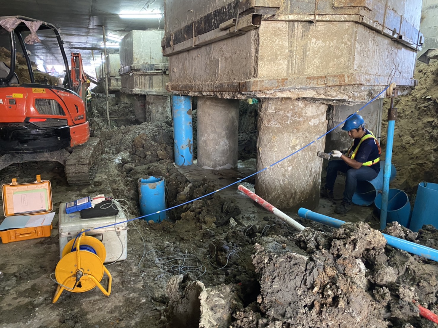
Side Echo Test
The Side Echo Test is modified method from normal sonic echo test (seismic test). The purpose of this testing is applied to evaluation the integrity condition and length of the pile foundation when foundation tops are not accessible. Due to the foundation top cannot accessible, the excavation beside the foundation pile is required until the pile side is accessible. The transfer block (steel block 500 ×500×250 mm.) shall be attached to the side of test pile by expansion bolt. This block is used to transfer the compression wave down to the pile. Before testing the tri-axial accelerometer geophone shall be attached beside the pile at approximate 0.15-0.20 cm. below the transfer block. After that the transfer block is struck by the hand held hammer on the vertical direction. The movement of the pile, caused by hammer impact stress wave and subsequent reflection is measured by the above mention sensitive accelerometer. The acceleration signal is converted to velocity and presented on screen as function of time. All result are stored for use in reports.
 cc
cc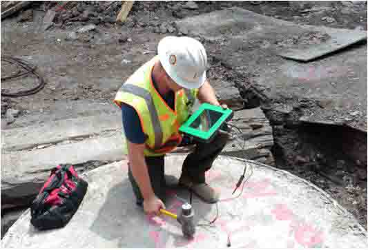
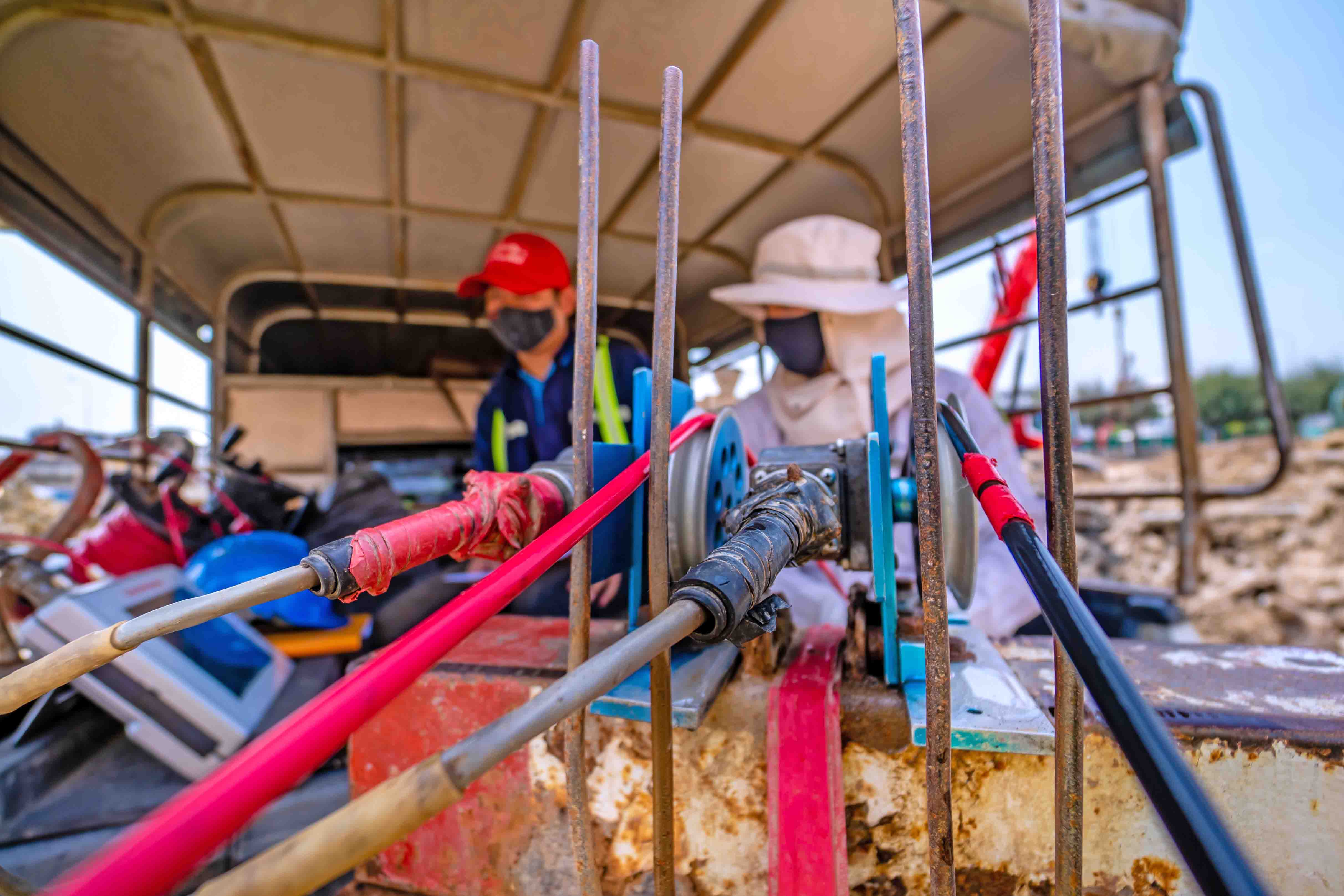
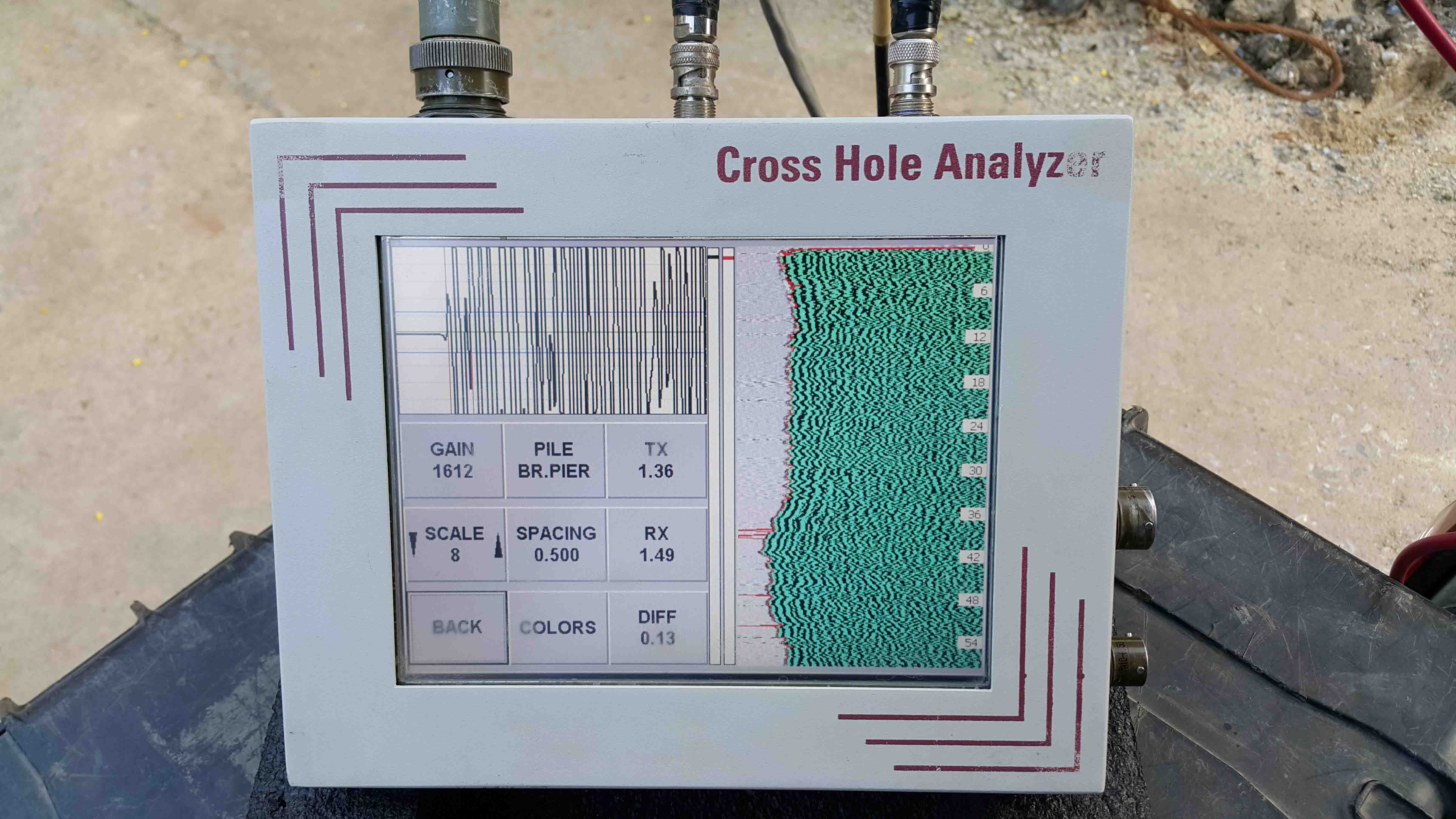
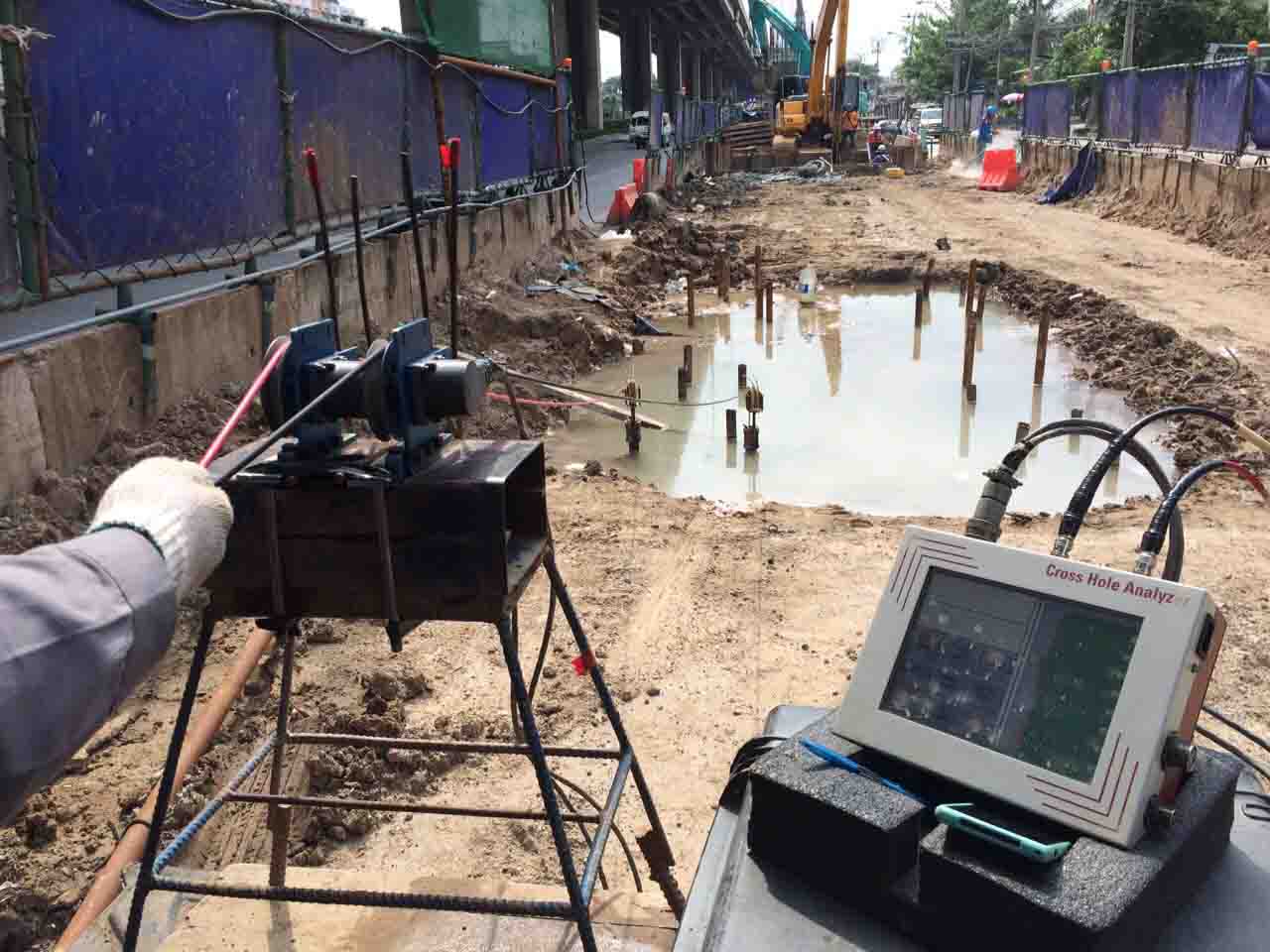
Cross Hole Sonic Logging Test
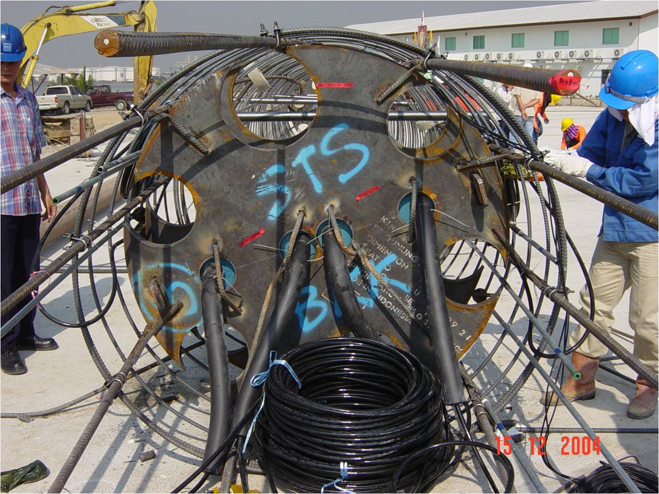
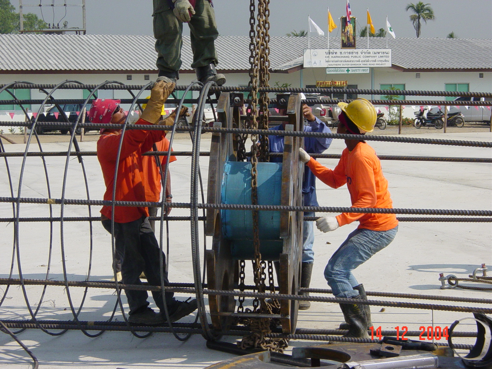
Cross hole sonic logging is a method to verify the structural integrity of drilled shafts and other concrete piles. This method is covered under ASTM D6760. The method is considered to be more accurate than sonic echo testing in the determination of structural soundness of concrete within the drilled shaft inside the rebar cage. This method provides little indication of concrete soundness outside the cage. Cross Hole Acoustical Testing normally requires steel (preferred) or PVC access tubes installed in the drilled shaft and tied to the rebar cage. Before the rebar cage is placed in the hole, the access tubes are attached to the interior of the rebar cage. The cage is then lowered into the hole and the concrete is placed. Steel tubes are preferred over PVC tubes because studies have shown that PVC tubes tend to de-bond from the concrete due to the heat of hydration process of concrete.
The tubes are filled with water as an intermediate medium. After curing for 7-14 days, a sound source and receiver are lowered, maintaining a consistent elevation between source and sensor. A signal generator generates a sonic pulse from the emitter which is recorded by the sensor. Relative energy, waveform and differential time are recorded, and logged. This procedure is repeated at regular intervals throughout the pile and then mapped. By comparing the graphs from the various combinations of access tubes, a qualitative idea of the structural soundness of the concrete throughout the pile can be gleaned.
2. Pile Capacity Test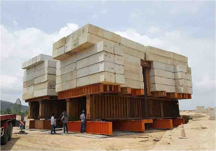
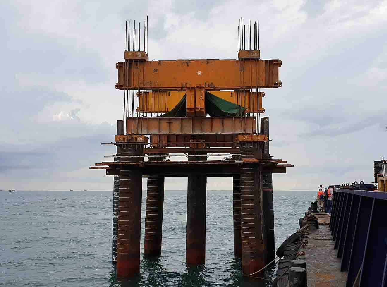
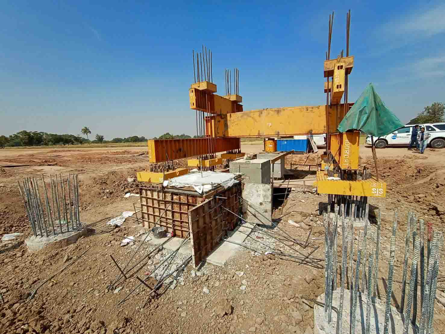
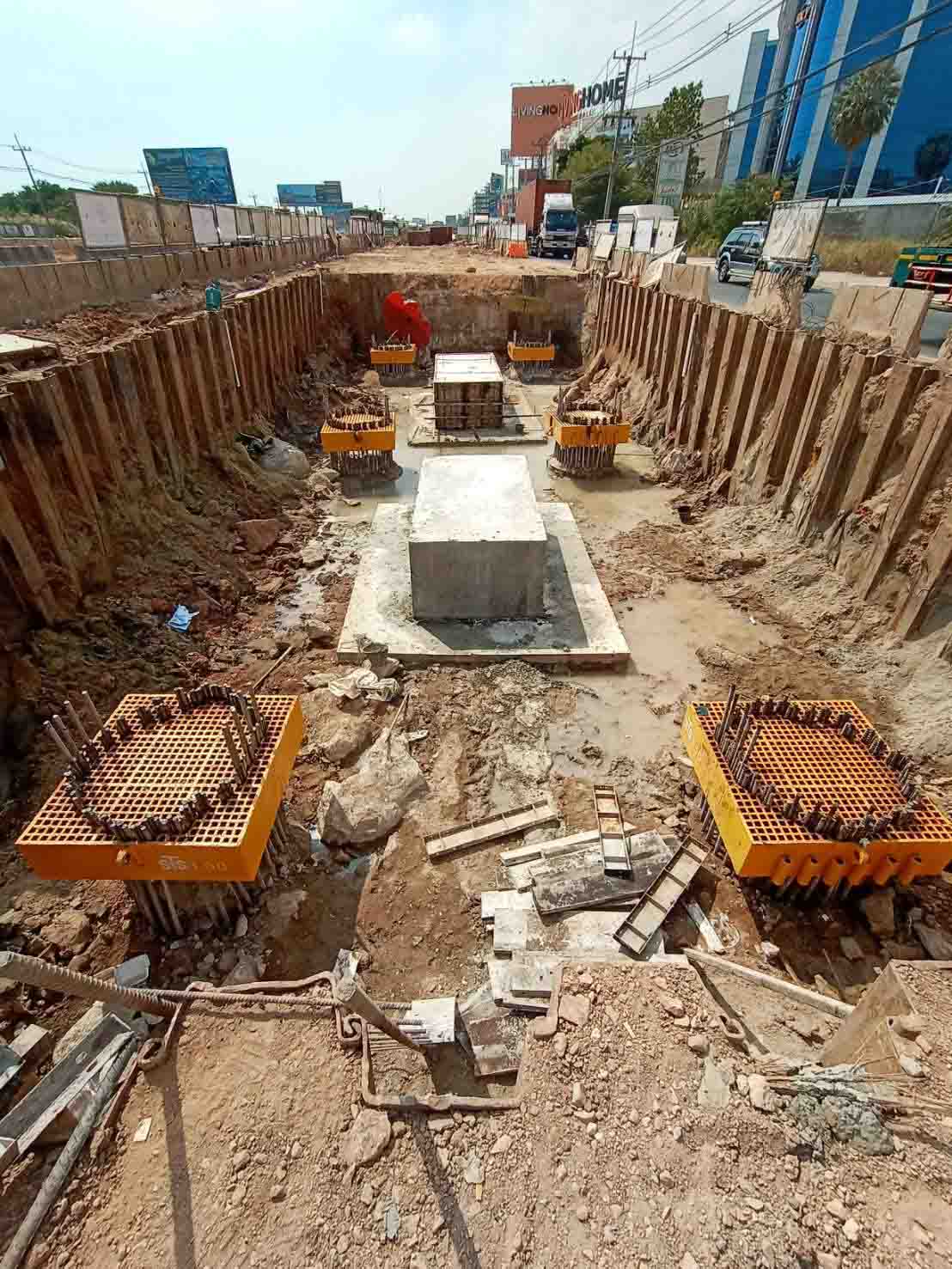
Static Pile Load Test
Full-scale static loading, conformed by ASTM D1143, is a widely accepted test method for authoritative assessment of deep foundation. Testing is typically performed once, and the result is considered the definitive answer regarding the pile’s load bearing capacity. The static pile load test is the most common method of testing the capacity of a pile and it is also considered to be the best measure of foundation suitability to resist anticipated design loads. The static load test involves the direct measurement of pile head displacement in the response to a physically applied test load. This test provides very reliable data for pile capacity. This method is applicable to all kind of pile types, over land or over water, and may be carried out on either production piles or test piles. Test piles are specifically constructed for the purpose of carrying out load tests and therefore, are commonly loaded to failure. Testing of production piles however, is limited to prove that a pile will perform satisfactorily at the serviceability or design load, plus an overload to demonstrate that the pile has some reserve capacity. Furthermore installed and measured instrumentation in to the test pile such as strain gauge, fiber optic and extensometer can available to determine the soil parameters in order to verify and optimize the design of the foundation for a structure.


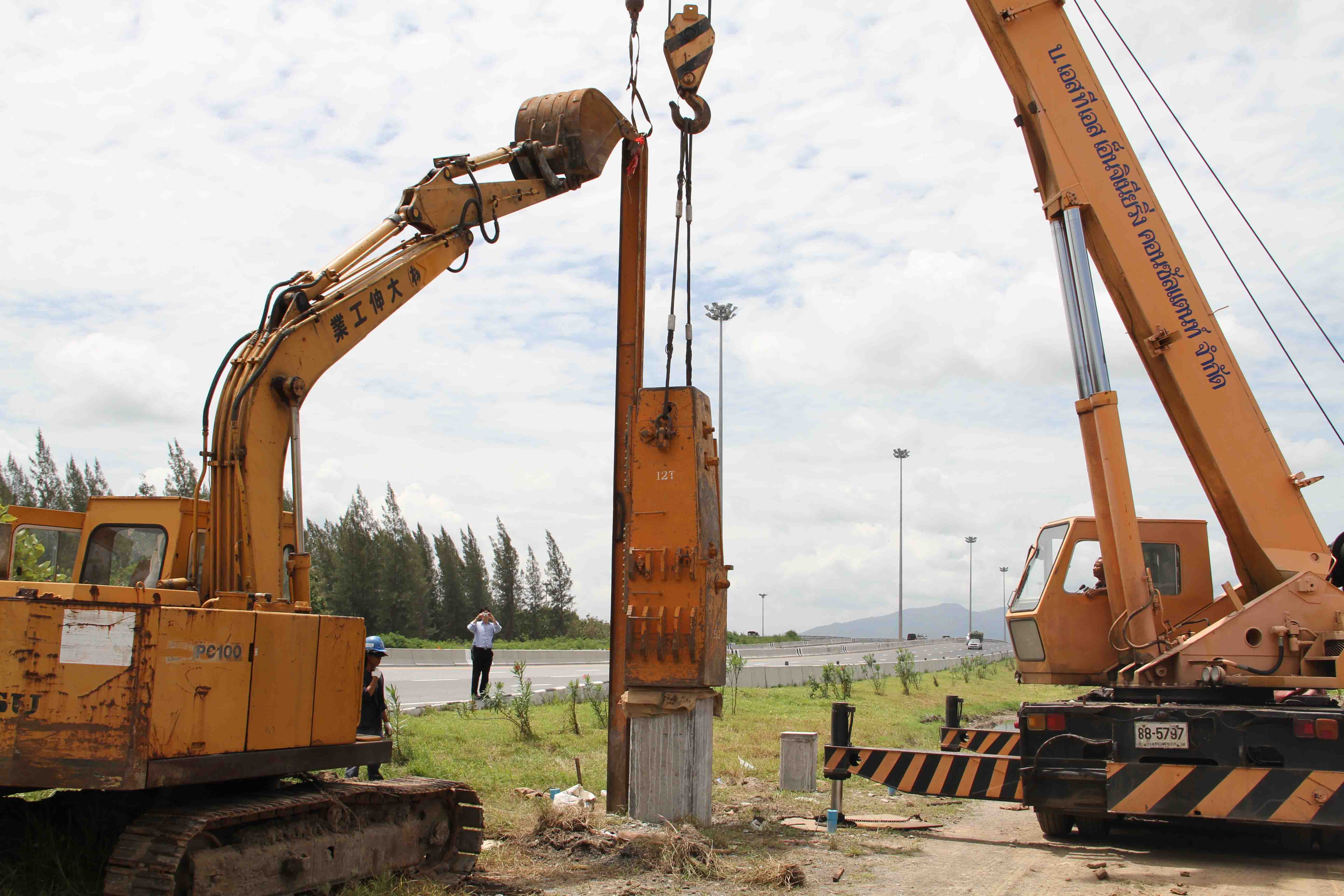
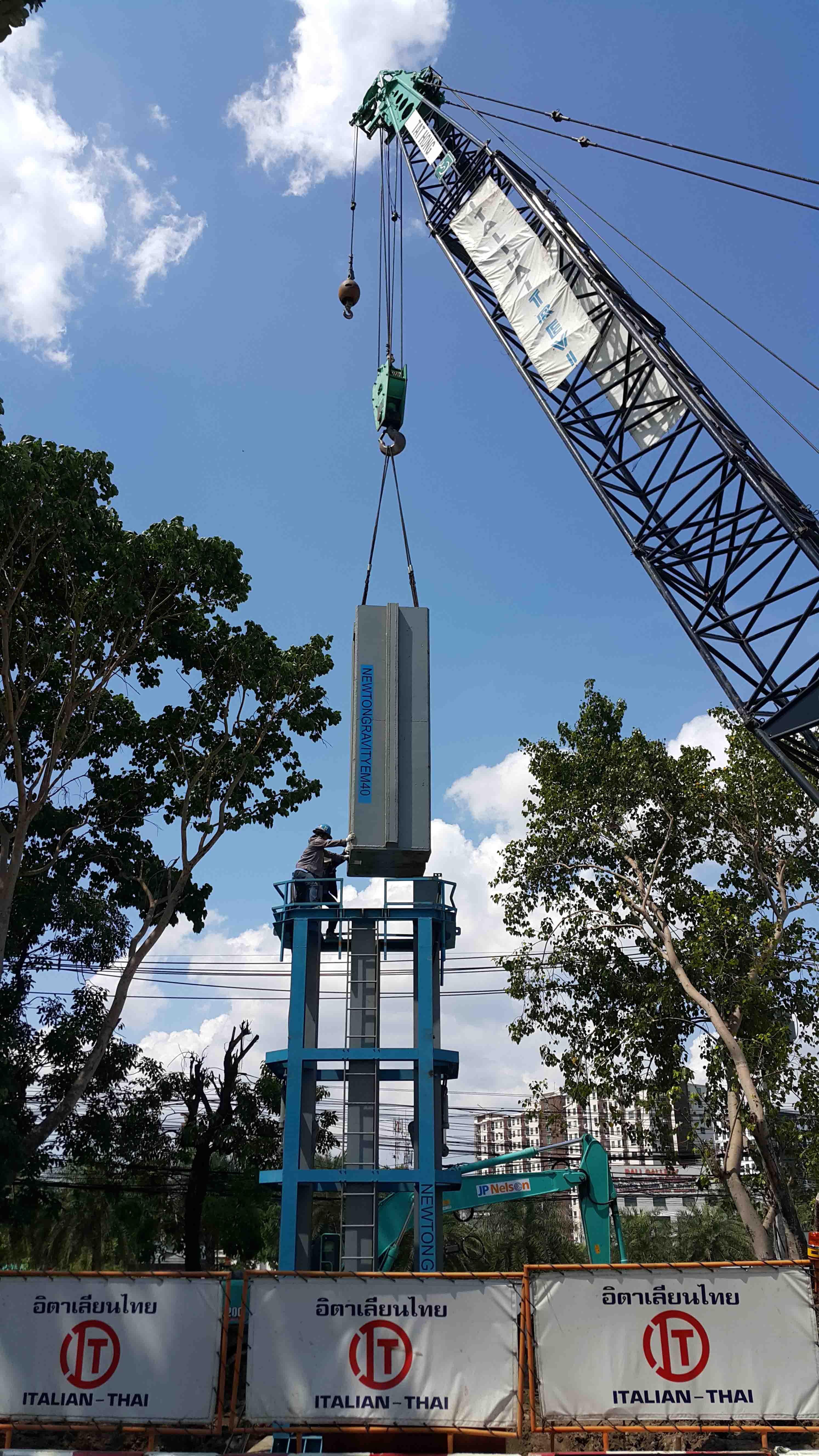
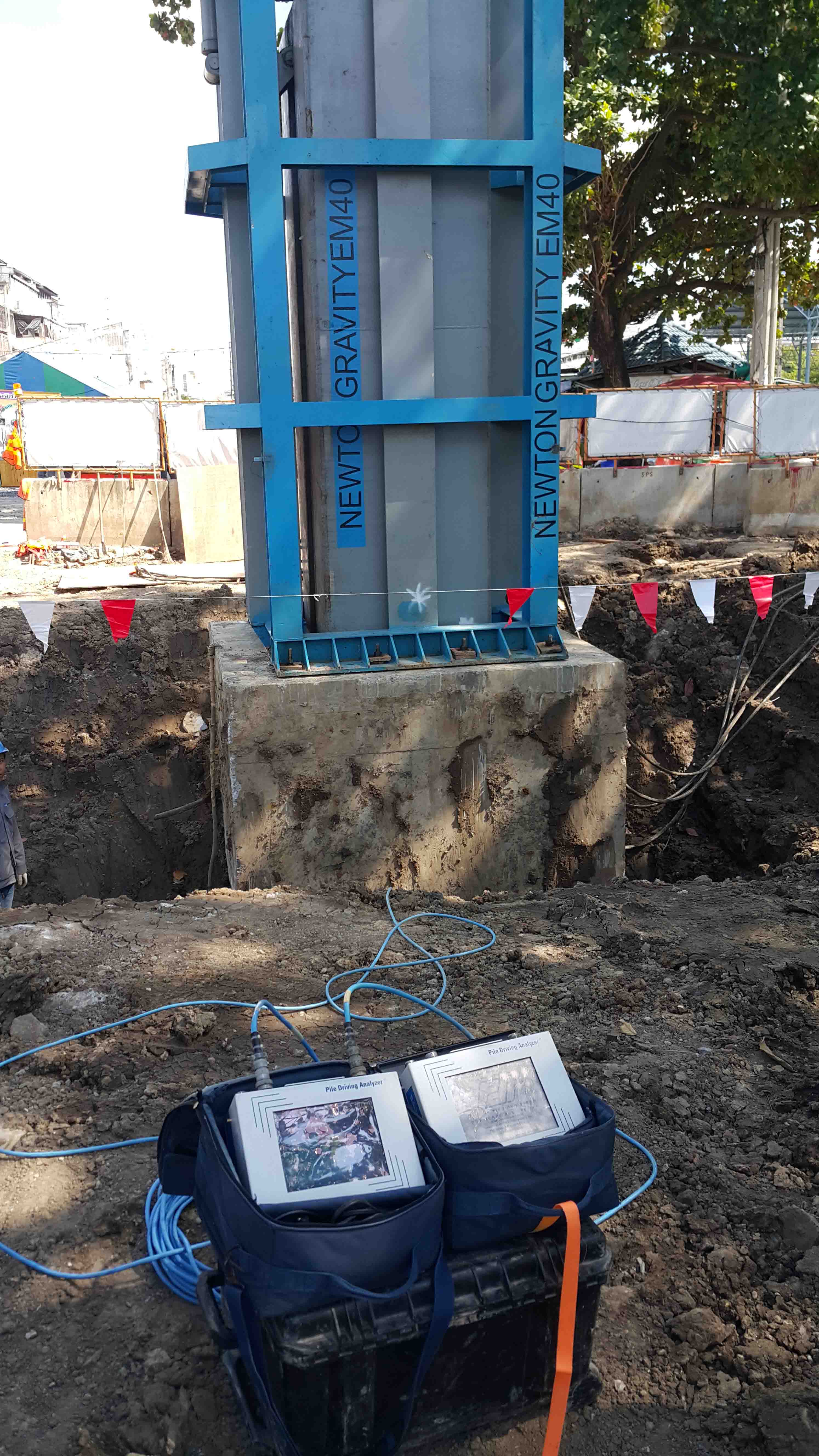
High Strain Dynamic Pile Load Test
High strain dynamic testing is a method of testing deep foundation to obtain information about their capacity and integrity, and in some cases, to monitor their installation. It is codified by ASTM D4945 Standard Test Method for High-Strain Dynamic Testing of Piles. High strain dynamic testing is called dynamic pile monitoring when it is applied during pile driving and dynamic load testing when it is applied following pile installation, regardless of the installation method. High strain dynamic testing consists of estimating soil resistance and its distribution from force and velocity measurements obtained near the top of a foundation impacted by a hammer or drop weight. The impact produces a compressive wave that travels down the shaft of the foundation. A pair of strain transducers obtains the signals necessary to compute force, while measurements from a pair of accelerometers are integrated to yield velocity. These sensors are connected to an instrument (such as a pile driving analyzer), that records, processes and displays data and results.
 .
. 
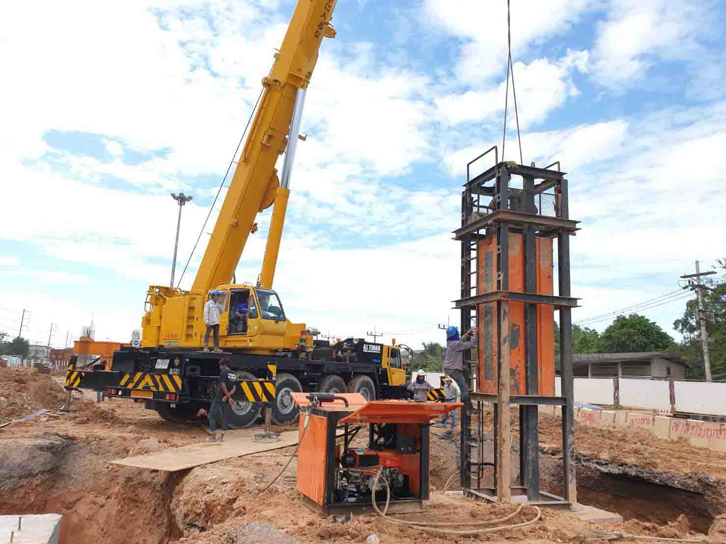
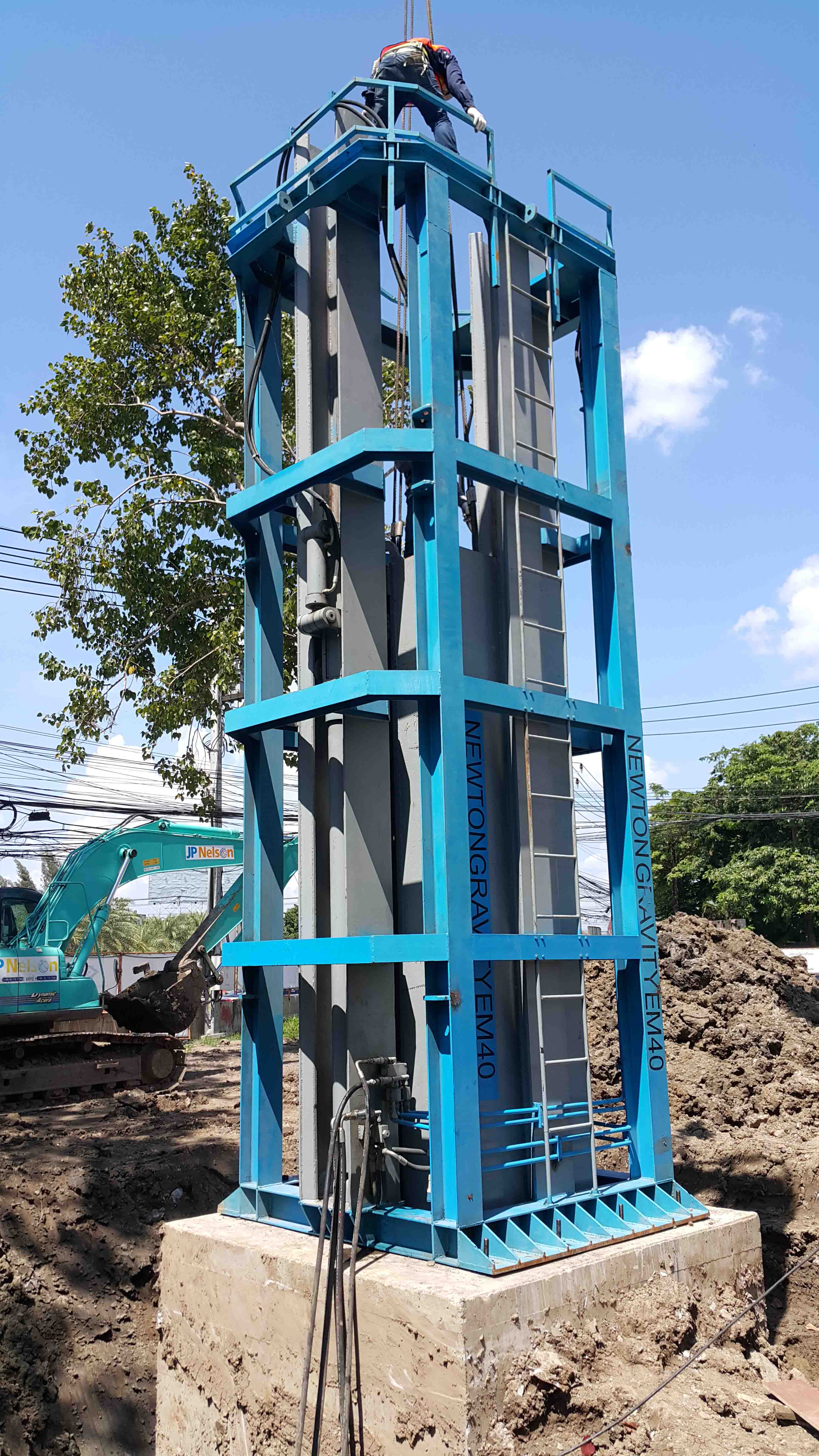
Bi-Direction Test
Bi-directional static loading test adopting load cells is widely used around the world at present, with increase in diameter and length of deep foundations. The BDSLT method of pile load test utilizes hydraulically operated Cells embedded inside the concrete of the pile. The embedded load cell is specially designed using built in hydraulic jacks. Pressure is applied to the load cell by hydraulic pump on the ground through the flexible hose embedded into the pile. The pressure in the load cell is measured by pressure transducer and the displacements are measured by displacement transducers which are connected to the load cell by telltale rod embedded into the pile. When loaded the load cell expands, pushing the upper shaft upwards and the lower shaft downwards, which would mobilize the side resistance and base resistance of the upper and lower lengths of the pile. According to relationship between the movements, bearing capacities of both upper and lower portion of the pile can be determined. Adding up the modified side resistance of upward pile shaft and the base resistance of downward pile shaft makes up the total ultimate bearing capacity of the pile.

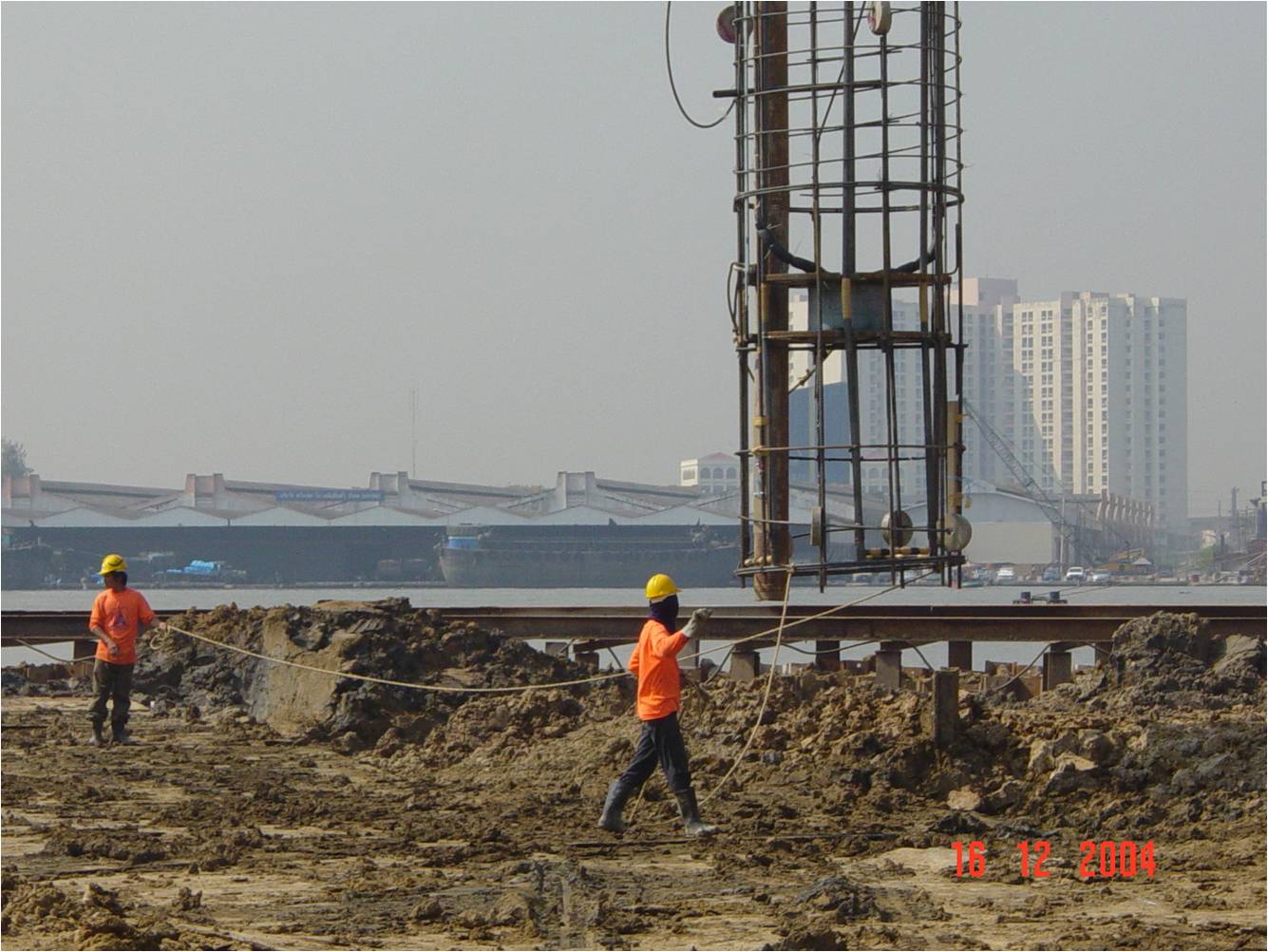
3. Drill Hole Monitoring Test
Single Shock End Test
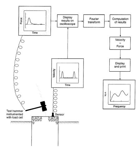
Single Shock End Test is the advanced method compared with the Conventional Low strain Seismic Test for testing the integrity of the pile foundation. In a Conventional seismic test, the basic concept in analyzing the result is based on Time-Based Techniques. The interpretation result displays in the relation between pile head velocity and depth of pile structure and the impact pulse is generated by Non-Instrument hammer. While in the Shock Testing the impact pulse stress wave is generated by using Instrument hammer which can record the signal in both of pile head velocity and force versus depth.
Frequency response method use modern computational techniques to analyze the composite wave from. The information obtained by using Shock Testing is shown in list below:-
1.Impact quality and concrete quality near pile top
2. Pile defect along the investigated length
3. Approximated pile length (if possible)
4. Characteristic mobility (M) and Pile head dynamic Stiffness (E’)
Cross Hole Sonic Logging Test
Cross hole sonic logging is a method to verify the structural integrity of drilled shafts and other concrete piles. This method is covered under ASTM D6760. The method is considered to be more accurate than sonic echo testing in the determination of structural soundness of concrete within the drilled shaft inside the rebar cage. This method provides little indication of concrete soundness outside the cage. Cross Hole Acoustical Testing normally requires steel (preferred) or PVC access tubes installed in the drilled shaft and tied to the rebar cage. Before the rebar cage is placed in the hole, the access tubes are attached to the interior of the rebar cage. The cage is then lowered into the hole and the concrete is placed. Steel tubes are preferred over PVC tubes because studies have shown that PVC tubes tend to de-bond from the concrete due to the heat of hydration process of concrete.
The tubes are filled with water as an intermediate medium. After curing for 7-14 days, a sound source and receiver are lowered, maintaining a consistent elevation between source and sensor. A signal generator generates a sonic pulse from the emitter which is recorded by the sensor. Relative energy, waveform and differential time are recorded, and logged. This procedure is repeated at regular intervals throughout the pile and then mapped. By comparing the graphs from the various combinations of access tubes, a qualitative idea of the structural soundness of the concrete throughout the pile can be gleaned.
2. Pile Capacity Test
- Static Pile Load Test
- High Strain Dynamic Pile Load Test
- Bi-Direction Test
Static Pile Load Test
Full-scale static loading, conformed by ASTM D1143, is a widely accepted test method for authoritative assessment of deep foundation. Testing is typically performed once, and the result is considered the definitive answer regarding the pile’s load bearing capacity. The static pile load test is the most common method of testing the capacity of a pile and it is also considered to be the best measure of foundation suitability to resist anticipated design loads. The static load test involves the direct measurement of pile head displacement in the response to a physically applied test load. This test provides very reliable data for pile capacity. This method is applicable to all kind of pile types, over land or over water, and may be carried out on either production piles or test piles. Test piles are specifically constructed for the purpose of carrying out load tests and therefore, are commonly loaded to failure. Testing of production piles however, is limited to prove that a pile will perform satisfactorily at the serviceability or design load, plus an overload to demonstrate that the pile has some reserve capacity. Furthermore installed and measured instrumentation in to the test pile such as strain gauge, fiber optic and extensometer can available to determine the soil parameters in order to verify and optimize the design of the foundation for a structure.
High Strain Dynamic Pile Load Test
High strain dynamic testing is a method of testing deep foundation to obtain information about their capacity and integrity, and in some cases, to monitor their installation. It is codified by ASTM D4945 Standard Test Method for High-Strain Dynamic Testing of Piles. High strain dynamic testing is called dynamic pile monitoring when it is applied during pile driving and dynamic load testing when it is applied following pile installation, regardless of the installation method. High strain dynamic testing consists of estimating soil resistance and its distribution from force and velocity measurements obtained near the top of a foundation impacted by a hammer or drop weight. The impact produces a compressive wave that travels down the shaft of the foundation. A pair of strain transducers obtains the signals necessary to compute force, while measurements from a pair of accelerometers are integrated to yield velocity. These sensors are connected to an instrument (such as a pile driving analyzer), that records, processes and displays data and results.
Bi-Direction Test
Bi-directional static loading test adopting load cells is widely used around the world at present, with increase in diameter and length of deep foundations. The BDSLT method of pile load test utilizes hydraulically operated Cells embedded inside the concrete of the pile. The embedded load cell is specially designed using built in hydraulic jacks. Pressure is applied to the load cell by hydraulic pump on the ground through the flexible hose embedded into the pile. The pressure in the load cell is measured by pressure transducer and the displacements are measured by displacement transducers which are connected to the load cell by telltale rod embedded into the pile. When loaded the load cell expands, pushing the upper shaft upwards and the lower shaft downwards, which would mobilize the side resistance and base resistance of the upper and lower lengths of the pile. According to relationship between the movements, bearing capacities of both upper and lower portion of the pile can be determined. Adding up the modified side resistance of upward pile shaft and the base resistance of downward pile shaft makes up the total ultimate bearing capacity of the pile.
3. Drill Hole Monitoring Test
Drilling Hole Monitoring by Koden, model : DM-604, 604R and 604RR, can measure and confirm for underground foundation work, the state of wall surface, pile diameter, deflection and incline, namely the "vertical accuracy" of the drilled hole or excavated wall. The deviation of the bore hole or trench from the perpendicular and any surface cavities in the bore hole or trench wall are measured. The ultrasonic measurement probe is suspended vertically from a cable and lowered into the object to be surveyed. At the same time, orthogonal waves are continuously emitted from the device and reflected from the walls. The reflected waves are registered by measurement sensors. The distances, calculated as a function of wave speed and reflection time, are presented in graphic form.
4. Parallel Seismic Test
Parallel Seismic Testing system is designed to determine the length and integrity of foundations when the top is not accessible or when the pile is too long and slender to test with echo techniques, or below a buried pile cap. Ultimately, Parallel Seismic testing provides information concerning the length and compression velocity of foundations and can be used on concrete, wood, and steel foundations. In Parallel Seismic test method, the exposed top of the foundation is impacted by an impulsive hammer to generate compression waves which travel down the foundation and are refracted to the surrounding soil. The refracted wave arrival is tracked at regular intervals by a hydrophone receiver in a cased borehole. The depth of the foundation is determined by plotting the first arrival times as a function of depth and observing the depth where a change of slope occurs. For this test method, a borehole must be drilled within 1.00 to 1.50 of the foundation edge and should extend at least 5.00 to 10.00 m. deeper than the anticipated foundation depth. The borehole must be drilled as vertical as possible, cased with steel or PVC pipes, capped at the bottom; and, in the case of hydrophone receivers, be filled with water prior to testing.